After
our last Speed-week trip in '12 with my somewhat hubristically named
'worlds fastest Weslake' debacle, I had to decide what to
bring to run next time. Clearly there wasn't any question of there not being a next time. The Weslake wasn't going to fly again; It was never going to get near a record and besides, I had gone off it somewhat. So
I sold the engine on and pondered. A XB9 Buell engine was originally
mooted, our friend PJ had one and we did a deal. But I really couldn't
get into the idea, and there was little progress, especially as it was never going to fit in the Weslake frame!
At the end of
March 2013 it was the 40th anniversary of me getting my first
proper bike; a BSA A10. Suddenly it all fell into place. The Buell plan
was ditched. It
was always going to be special-construction, but this time we could run
in Vintage. Blown. Methanol. Looking at the record book, I saw there
was no record set for the 650 or 750 classes.
So
we set about sourcing some BSA stuff. After a false lead or two, we
(thats me & David who crewed for me last time and will co-ride this
time) hit the Newark swap-meet and got some basics:
We
also met an old boy who used to run sidecar grasstrack. Paul Grayson in
West London. He used to cast his own parts and had a couple of blank
alloy cylinder castings. We bought one: Not
the tidiest casting in the world, he never intended to win shows, just
races! But the alloy is good and properly heat-treated. Theres also a
lot of it! no question of these breaking. That gets us out of trying to find a good thick-flange original pair of barrels, but leaves us with a ton of machining.
In
mid April I topped & tailled and rough-bored the cylinder casting
in a spare afternoon. Cored cylinder holes were way off - too close
together and one was a bit skewed. Didn't clean up until I got to 72mm.
Good job we didn't want the stock 650 70mm bore!
The guys on the A10 forum were super helpful. One
guy-Julian-who restores Lagondas for a living is building a street
scrambler A10 has made his own billet crank & barrels. He offered
to help us with cylinder drawings. Another bloke, Muskrat, had a
twin-carb ally head. Wanted to swap for a 4-spring clutch. Only
problem, he's in OZ! But then Julian stepped in again and offered to
send a spare clutch of his to Muskrat who could then send us the head.
How generous was that? He wont even let me pay shipping.
We
decided to use a Norton crank, and another good ol' boy, Baz, came up
with a 750 commando one. Why? they're 89mm stroke as opposed to 84mm.
With a 73mm bore, it gets us 744cc. Plus, big-journal A10 cranks are rare and fetch big bucks these days.
Early
May, got some work done on the crankcases. Main-bearing upgrades;
a notorious Achilles-heel on BSAs. The stock timing side one is just a
bush (left in pic) A poor setup which fails regularly and bleeds off
oil pressure that could be going to the big-ends. There isn't enough
room to bore out for a decent size ball or roller bearing; the solution
is a special INA combination ball-roller bearing: First, you have to set the crankcases up true & level in the mill. So I took a light cut off the timing face These
cases are 55-odd years old. Nothing is properly true on them! I
knew they'd be out of line; I set them up & centred on the
drive-side bearing bore, then removed the LH case & tried to centre
up on the opposite bearing bore. Turned out to misaligned by about
.006" (timing side hole was out-of-round too!) Decided to take up
the difference on the drive-side one to avoid gear-mesh problems on the
timing side. Bored the case to take the new bearing: Then bolted the other half back on and took a cut out of the oil-seal bore:
Which
gave me something to centre up on when doing the drive side; using a
Norton superblend bearing, which is 10mm bigger than the stock A10 one:
Finished bore: Got
the oilway mods on another spare afternoon. The BSA has the oil to the
big-ends fed thru the timing side main journal and round a groove in
the journal to the pressure release valve. We're converting to end-feed into the crank, so a way has to be made for the oil to get there. There
is a dowel that locates the inner timing cover which will be put to use
here. First up, drill a hole across to the oilpump outlet hole:
A bit heart-in-mouth hoping it doesn't break thru the casting anywhere! It didn't. Then tapped the end for a 1/8bsp pipe plug Then the case was bolted down timing face up to drill the dowel hole thru:
Lastly, set up the other way up & cut a groove in the bearing hole to re-connect the pressure release valve: Time
to machine the crank; needed turning to accept BSA timing gear &
oilpump drive. Also, an extension piece had to be pressed on to get the
full width for the main bearing. Oilpump drive is LH thread, so had to
screwcut the thread upside-down.
And in the cases (in dummy bearings); endfloat was good at .010": In
June, we drove over to see the event at Pendine Sands. But
Saturday morning, we drove up to Aberystwyth to see the guys at SRM. A very impressive setup they have there; they can do every aspect of bike resto except for plating. They gave us the grand tour. I
handed over a list of stuff we needed and they went off to find it. I
had already brought up the subject of sponsorship; I left it up to them
how much they wanted to help - anything from a bit of discount
to...well whatever..... The box of parts appeared, and Gary & Geoff there went off to confer. They came back and said 'right, we'll do 10%' I wasn't going to show any disappointment and said 'OK' They then chuckled 'Nooooo, not really! you can have it for nothing'! At which point we were all overcome with gratitude. Heres what we got, about £500 worth. In
other news, we got wheels. Thanks to Mook for donating the front one.
They're off BMWs and have a unique spoke arrangement that allows
tubeless tires.
And back from chrome powder coating: On July 1st, a package arrived from the states - big thanks to Drift for helping to get this to us..... Wiseco pistons: These
are much shorter than the stock ones, only 25mm compression height. So
although we're running a 5mm stroker crank, the rods will still need to
be 0.265" longer than stock.
Cam: I
had Megacycle in California grind this; its based on one of their
catalog grinds but has a bit more lift - 10mm! almost 2mm more than the
stock 356 cam. But less duration! Only want minimal overlap with a turbo. Compare the new one (left) with a stocker:
Lastly, beehive valve springs. Actually intended for a Ford 4.6L SOHC V8. Just got to find some colletts which will work! It
was at this point that some money became available. I had been
building a '79 Trans-Am with a 540 inch BBC for some time. It was
progressing slowly what with all this LSR stuff. So when I got a
reasonable offer for the uncompleted car, I reluctantly went for it
(I've never had a really massive big-block before - dont suppose I will
now) So with this windfall, I asked Dave Branch if he'd do me a
billet crank, and he agreed to take it on. In doing this, I was able to
specify a few things that the Norton crank didn't have. Anyway, with some customer work out of the way I was able to get stuck into it again. I
needed to assemble a mockup engine assy, so I resumed work on the
barrel casting. I did it the old fashioned way. Took the
top-end off the Bobber and plotted the top & bottom bolt patterns.
The stock barrel was all over the place! fortunately, when BSA designed
the A10 they mostly used rational measurement units - sixteenths of an
inch here! So figuring out what the dimensions should be was easy.
Top bolt pattern - tapped the holes 10mm rather than 3/8 BSF:
Bottom holes: And doing the spigots on the ol' rotary: The rearmost bottom holes ended up too far back and so I'll need to build it up with weld. The last bit is the hardest; doing the cam-follower bores and the pushrod tunnel.
Doing the cam follower bores was a bit heart-in-mouth as screwing it up would junk the whole job. First thing was to bolt the stock barrels onto the cases with a pointer in a lifter bore to check for misalignment: Not too bad, maybe ten thou out.
Set
the mill up using the stock barrels. Drilled the angle plate so I could
bolt the stock set on and then the ally casting in the same place:
And there's the followers in place! Got the fit just about right...phew!
Time to do some ally welding. Built up the rear barrel flange and got started on ol' Muskys head. Added
bosses for exhaust studs. Dont think shove-in pipes will work with a
turbo! Also welded up one of the exhaust valve-guide holes as it was
hugely oversize, and plugged up some damage to the gasket surface. While it was cooling down, I set up the cases and bored out the cam tunnel. Our superduper cam was too big for it!
Thought I'd let that ally welding age for a few days. Plenty else to be getting on with. Before
I could set up the engine/gearbox I needed to know primary length.
Primary drive was something that could be done in a number of ways. Definitely
wanted belt drive; could have spent north of £400 on a Commando kit,
but with the billet crank, I have the option to have a splined sprocket
shaft (which I certainly will choose! - I hate tapers) Also, the
Commando clutch was good in its day, but there is better stuff. Such as
the Kawasaki GPZ1100 clutch I've had kicking about for decades! The
good thing about the Kwak clutch is that both the basket and the hub
are rivetted to their respective drive parts. So grind off the rivets
and you can attach it to anything..well almost. I bought some blank
pulleys and a 2" belt from Bearing Boys along with some bearings &
circlips. Here, I'm measuring the installed length between centres: Sadly,
the big pulley wasn't solid, but was webbed with big centre bosses, so
I machined the middle out and turned up some steel: Then welded it all up and machined it:
Completed: End of August, it was cylinder head time, amongst other things... Wasn't
looking forward to doing this! All the valve guide holes were tapered
and well oversize, and the valve seats were for the small A7 valves.
Too small for our SRM Rocket Gold Star valves. I'd already welded up the worst guide hole (over 1/16" oversize!). I set the head up on the adjustable angle plate... ..And
remachined the guide holes and machined out the seats. A horrible job;
the stock seats are cast-in and are an irregular shape. They're also
pretty hard. This meant that some of the old seat material was
still present in the finished insert bore. The hard seat material cut
smaller than the remaining ally. I got it as good as I could by taking
many small cuts. Heres the head ready for the new seats: before
doing this, I did all the port-enlargement that I needed to do in the
valve-bowl area. A lot easier without the guides in.
Putting new
seats in an ally head is a bit fraught at the best of times. You need
7-8 thou interference fit or they'll come loose. This means getting the
casting bloody hot (or chilling the seats in liquid nitrogen - not
something I happen to have!) And then pounding them in. Got 3 of them in, but broke one insert so had to take a ride down to Cambridge Rebores on Friday morning to get another. This
of course meant having to re-heat the head. So in the meantime I got
the new guides ready.They had to be custom-sized, so I turned the
exhaust ones from a small bar of Colisbro and made the intakes out of
some Rowe shovelhead ones. made them with 4 thou interference. Probably
a bit too much as they were a bastard to get in there! They're not
coming out! Guides in: Seats in: Once
cool, I had to ream the guides to size. There was about 10 thou to come
out of the exhaust ones and it soon became clear that my little
adjustable reamer wasn't going to do the job. This Colisbro stuff
doesn't like being cut, and tends to machine undersize & sieze the
tool. I actually broke the reamer. I do have a 5/16 machine reamer
but was scared I'd get too much clearance, so I tried it on an offcut
and it came out just right. Fortunately, I'd left the mill setup from
when I'd machines the seat & guide holes, so it was simple to bolt
the head back in and run the reamer thru. Thankfully, they came out spot-on.
Next
day I finished blending the new seats to the ports and then got the ol'
valve-seat cutting gear out to finish the valve-job. Did a 3-angle job
on the intakes (I already did the first angle in the lathe before I
fitted the seats). On the exhausts, I had bored them to the max size I
could, so no room for a 60-degree cut. A bit of lapping, and its good
to go, apart from some port opening-out on the intake side. Checked
valve-stem protrusion expecting to have to cut the seats some more to
get them to spec, but found they were all within 5 thou of each other!
They're actually about 40 thou less than what I think is stock (1.8")
at 1.760" I most definitely wont be sinking the valves deeper to get
the 1.8" spec! There it is done: Next; setting up the drivetrain...
Linking
up the engine & gearbox. I'm using a motorplate behind the primary
so there is a support bearing behind the clutch. Eliminates the massive
overhang on most old Brits; Must have been loads of flex when power was
applied back in the day. Used 10mm ally plate. I knew the distance
between engine & box (see above) So i bolted it to the mill and
first bored a hole for the crankcase register and then one for the
support bearing. Then I clamped the gearbox shell over the latter hole and using a turned plate to centralise it, I plotted the mounting holes:
Did the same for the crankcase: Did the necessary drilling and then using the same X & Y coordinates, I drilled the engine plates:
Heres the assembled cases in the jig. Just plonked in there at the mo' Got to figure out the best position yet. Before
I could set the engine up properly, I had to get the sprocket line
established. Which meant getting a sprocket on the rear wheel; which is
a BMW front wheel. Not the most straightforward job!... Interestingly,
BMW - 'uber-germans' who probably sneer at our outdated imperial
measurements, have made the bolt pattern PCD of their front
discs.....8"! :lol: Not 200mm or anything rationally metric (unless
203.2 mm is rational!)
Meanwhile, some shiny bits turned up. Custom length con-rods with Triumph big-end size & 17mm pin holes from R&R in Illinois. Big thanks to Drift for handling logistics! Some progress made on the frame. Halfway thru doing the engine mounts here.
OK,
you're thinking 'WTF? has he gone nuts?, a gooseneck??? aint this
supposed to be serious? What next? 6-bend pullbacks?' Well, there's method in the madness; The turbo has to
go somewhere, and in front of the frame tubes looked better to me than
anywhere else. So the gooseneck allows this and keeps it from
interfering with the front wheel. Dont worry; it'll be as tough as the Forth bridge when I'm done! There you go; looking a bit tougher!
I finally gave up trying to get Avon to sponsor us. Loads of calls & emails but couldn't get a 'yes' or a 'no'. So I bought some. A local car tyre place supplied & fitted for the same price as buying off the internet. We have a rolling chassis now:
Rolled up an alloy oiltank: Used
the filler neck off the old Weslake one. Ends are domed - I had 2
pieces of domed ally from a pair of polished belt drive covers; one
small, one large. So I beat out a matching pair. The smaller ones will
go on the intake plenum Couldn't
finish the ends until the inlet was done. You can see the dump valve
underneath; its a Forge dump-to-atmosphere one off a Subaru Impreza.
Had to machine up ally carb flanges to take the mk2 Amals. From
the aborted Buell XB9 project came a set of stainless headers which
were perfect for making the head-to-turbo exhaust. David sorted
out all the stainless flanges. Intercooler is a cut down one from a Range-Rover that was kicking about. I made end tanks for it. Took all afternoon; would
have been easier to make them with flat sides, butI wanted them rounded
off and shaped to help flow.
Whilst waiting
on other stuff I made a start on the tank as David needed to know
about fuel pump position and whether we can get it in the tank. I
wanted the bike to look a bit BSA-ish, so a conventional tank is needed.
Mounted way low, it wont affect the riders ability to hunker down too
much. Its an old BSA one bought for £20 a few months back. Obviously it wouldn't fit this frame without some work!
Heres a pic of the tank done & mounted Turbo setup almost done, just the oil system to do; Oil tank is underneath.
Exhaust is simple. Arrow points to oxygen sensor boss.
Fuel
system will sit all together in front of the tank. David sourced a
Mallory pressure regulator which allows us to run an EFI pump and
regulate it down to 4 PSI. It has a boost-reference port so pressure
keeps 4 psi above whatever boost pressure we have. David also ordered an electric fuel shutoff, and lined up a fuel pump generously donated by the folks at Fuel Performance. We
now had all the major fuel system parts. We now had to figure a mounting setup that'll work
and allow sensible plumbing...Which is never straightforward...
The cases are the weak spot in this engine. Not unknown for old brit cases to break just below the barrel flange. So
some extra support needed to hold things together. One or two
substantial studs each side coming up from the crankcase; the primary
plate on the LH side and the yet-to-be-done billet inner timing cover
on the RH. Thought awhile about this, its easy on a Triumph with its
separate rocker boxes; having 2 separate pieces would tend to bend the
head-studs, and a bridge that goes over the top of the rocker-box would
be complicated & in the way. The answer was to mill away the fins in the middle of the head to make room for a bridge piece.
Dug out a billet yoke offcut which was perfect for the job:
A card pattern & a bit of bandsawing had a blank piece. Loads of milling & fettling.
And its done! Only took 10 bleedin' hours!
We had a good example of the law of unintended consequences...... Having
made the head brace, it soon became clear that spark-plug access was
now impossible! I really didn't want to be taking the tank off to get
at the plugs, so drastic action was called for: Getting the holes in the right place was ummm.. interesting!
A lot of small uninteresting stuff to do, all the head studs & nuts for example:
Got
fed up going thru the ARP catalog trying to find something suitable.
Wish they'd list their studs in order of sizes as well as 'kits for
xxxx vehicle' I know they have a form you can email with what you need,
but they aren't very forthcoming with answers. So; I made the studs
from grade 12.9 allen bolts. Cut the heads off & screwcut 10x1mm
threads. I wanted to use fine threads to keep the root size as big as
possible, what with cut threads being less good than the rolled
(10x1.5) threads, so that the ones I cut were stronger than the factory
rolled threads.
I made a few more than needed (bound to lose
some nuts! ) So I did a bit of testing. drilled &
tapped a 10mm thread thru a bit of 1" ally plate, screwed a stud in and
with a spacer to replicate the head thickness, I set to with the torque
wrench & micrometer. Interesting; at 20 ft-lbs, the stud
stretched .003". At 40 it stretched .005", 48 = .006". And so on every
5 ft-lbs or so stretched it another thou. intercooler Each time, I slackened it
off before the next 'pull'. At 60 ft-lbs the stud had permanently
stretched half a thou, the point at which ARP fasteners reckon a
fastener should be scrapped. Kept on at it, to try & make it fail. 80 ft lbs pulled the stud .011" but it never made it to 90.
It
broke where you'd expect, at the end of the coarse thread. My cut
threads came thru OK. At all times, there was only 1xD of thread
engagement in the nut. So; conclusions: the studs are good enough
for the job, and to get the optimum stud-stretch, which is 6 thou, a
torque of 40-45 ft-lbs is needed. The thermal expansion of the ally
head means we should stay on the cautious side.
Inner timing cover. A bit time consuming doing all
the holes. Here I am doing the hole for the intermediate pinion bush:
Billet inner timing cover turned out to be a bit of a long job what with the
(RH) head hold-downs too. I added a few more holding-down fastener
locations to cope with the pull of the head studs, including a 3/8 bolt
where the old breather hole was. Note the stock rotary breather is
deleted and replaced by a reed-valve (off a Piaggio scooter!). This
means it'll exit positive crankcase pressure whenever its there rather
than when a valve opens. Exit is at the top.
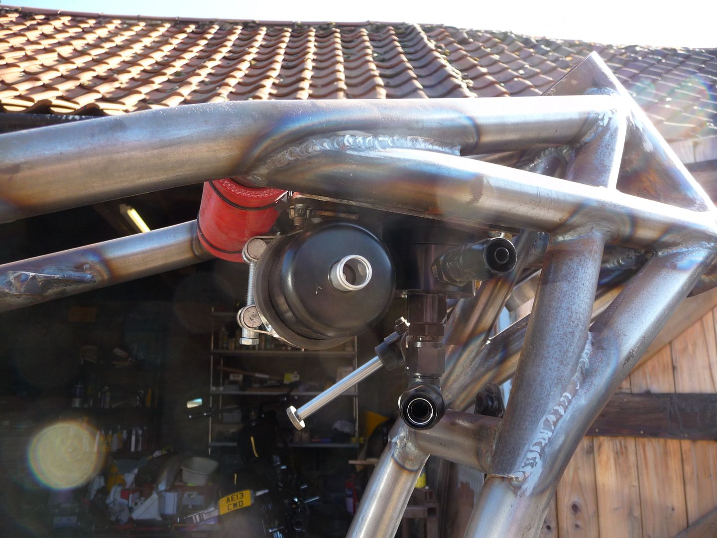
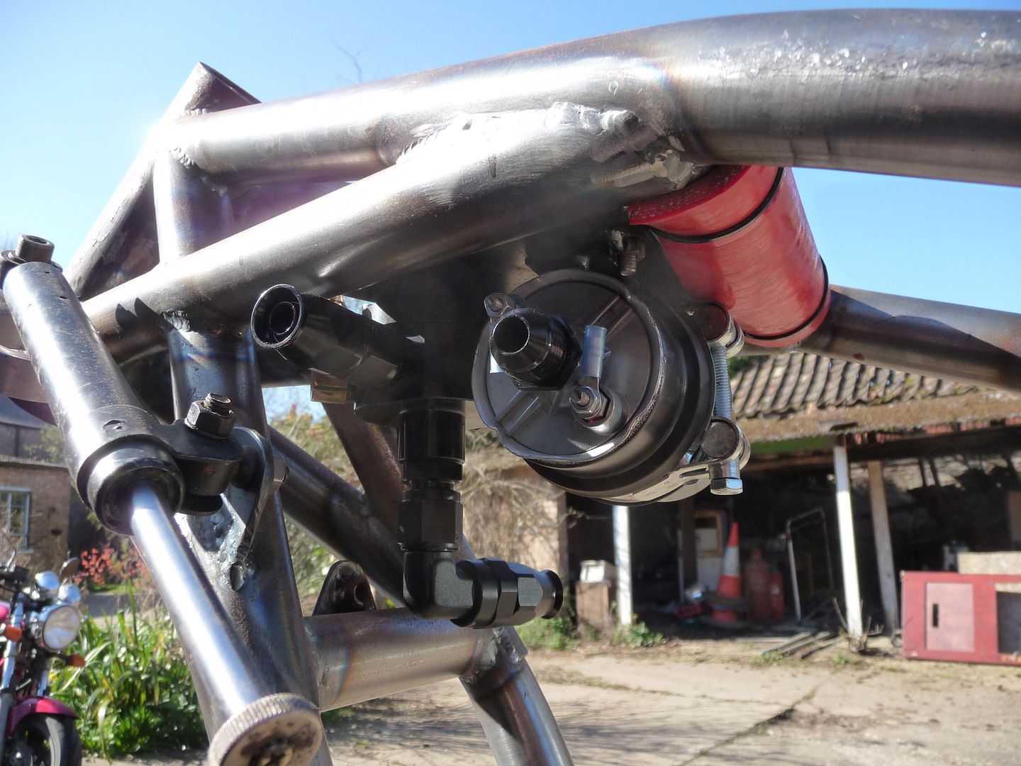
The
turbo oil pump is a cut-down sportster one. I shortened it and just
left the old return stage. Blanked off the original outlet and turned
off the drive gear & welded on a belt pulley. The job was complicated by the need for a pressure relief valve which I had to make. First
I worked out that 40psi acting on a 12mm piston made for a pressure of
about 7.5 lbs. Found a likely looking spring and set a 7.5-ish lb lump
of steel on it which compressed it 10mm. So I machined everything so
that with 10mm piston movement, the excess pressure bleeds off back
into the pump inlet side.:
Assembled:
And with the drive in place:
Done the final piece in this timing-side jigsaw...the crank oil feed. Just a small chunk of ally, but a whole days work!
There will be an oil seal behind the circlip: With most of the drivetrain engineering done, I got started doing cycle parts. The
original idea was to do a seat/tailpiece. But the rule change that
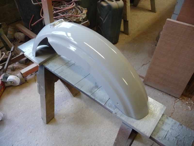
requires the rim to be fully visible from the side caused the change to
a conventional fender & seat. Regular customer Scouse Tony gave us an unwanted alloy Zodiac one...but it was 11" wide! So I cut 6" out the middle. Simple
stainless sissy-bar is there purely for lifting & pushing duty, of
which there seems to be quite a bit out on the salt! Rear-sets are straight off the Weslake. Brake torque arm, seat base & battery carrier also done. And I re-did the rear tank mount setup. Just too ugly before. Just the fuel system parts to mount before powdercoating. At this point we were informed that we had to get the bike ready for shipping by the
end of May, which was about 3 weeks sooner that we reckoned on. I've had to attend to paying work, so David took over. He got the fuel system stuff mounted:
The cylinders were nikasil coated, and a heap of bits were polished, some of which went off for anodising.
With the anodising
back David & I did a bit of assembly. We got the Norton gearbox rebuilt and got it and the forks on the frame:
Just in the nick of time, Dave Branch came up with our lovely billet crank!
Assembly & wiring.
A few more small tasks to do before we try fireup. Some pics:
Things weren't looking greatat this point. We had it running a few times. We couldn't stop it flooding. Dyno session at Krazy Horse was abortive. Amal
carbs dont like fuel pumps! even adjusted down to 1psi or less its hit
or miss. Reducing float-needle seat from 4mm to 2mm hasn't helped. We
could go down to 1.6mm but I dont think thats enough to feed a blown
methanol engine. Floats are too small. Not enough buoyancy. Only
a week away from shipping date...what to do...? Decided to try starting
& idling without the fuel pump on, and only running it once
underway....might work!